![]()
CauseF manual (v. 5.0)
Contents
Overview
Default settings - Set default options for all modules
Grid - Key points, Settings window, Grid window
Spheres - Key points, Settings window, Spheres window
Planets - Key points, Settings window, Planets window
Bones - Concept, Process, Key points, Settings window, Bones window, Bones properties window, Presets, Tips and hints
Contact and bug report
Copyright and credits, references, history
Bones
Extensive tool tips should allow you to run the program straight away. For more details about the how and why see below. See also Tips and hints.
Concept
Process
Key points
Settings window
Bones window
Bones properties window
Vector presets window
Tips and hints
Concept
Compare the general appearance of a column on a building with that of a bone. In principle both are the same load-carrying structures, yet bones have a distinct shape. So much so that from a fossil often the species can be deduced, the overall size of the animal, whether it was a predator that runs or jumps, in fact where in the body that bone used to be situated for this or that purpose. Why the difference?
As mentioned on the page CauseF program, in nature species evolve in a nonlinear fashion. A certain influence affects the relevant elements in its neighbourhood, which in turn influence each other and so on. That ongoing process moves towards a kind of equilibrium where the functional elements constitute factors, each ending up in terms of size and potential within a certain range that accommodates its surrounds in a similar manner. The same goes for the skeleton, and so a thigh bone for example can grow to a certain size in order to enable the animal to hunt its food that much better. More food means more energy and a more powerful species. It could grow larger still, but for the animal that would mean needing more food again and if not available the increased size would turn into a disadvantage and thereby diminish the survival prospects of that species.
The bone grows larger as a response to the forces acting upon the animal as it makes use of its skeleton, accompanied by the enhancing and/or mitigating factors touched upon above. Those forces will come from certain directions and as such exert their influence on the organism. The resultant vectors (direction, magnitude) lead to the eventual appearance of the bone, allowing us to discern its use - a thigh bone, a forearm, a fin, etc. The direction is defined by the action the bone performs (walking, running, jumping, swimming) and the magnitude by the load it is subjected to (the weight of the animal's body, the size of its prey, any resistance being encountered). Hence this subsystem arrives at an equilibrium, but a balance which is constantly subject to change.
And here is the difference between man-made structures and bones. Engineers ascertain the loads a column is meant to withstand and employ the relevant calculations, a top-down approach. In nature the skeleton evolves from the inside out, a bottom-up approach, and the result is a certain bone that is useful for its particular purpose with its own distinct shape.
In the Bones module the effects of force vectors are applied such that, given the material attributes of the shape (which starts out as a plain cylinder), the shape does not break or bend without being able to revert to its original form. This means that the cylinder made out of plastic for example may need to be made thicker in order to withstand a force from above, including the ability to carry its own weight. The load from above, combined with the increasing innate weight as we move from the top downwards, leads to an appearance resembling a bone (then again, the initial radius at the top may be wider than really necessary, and so the width will decrease towards the bottom because the material is able to withstand the load anyway). CauseF gives the user 10 force vectors to experiment with, pointing in whatever directions with whatever magnitude, and so the result will be a function of all those influences upon the cylinder. In the end the shape may not look like a - conventional? - bone at all any more. Note that additional modifications due to the need for joints at both ends of a real bone have not been taken care of.
The pertinent material attributes are, density, compressive strength, Young's modulus, shear modulus, and yield strength (what these mean is explained under Bones properties). There are seven broad material categories, each with its own presets, namely bone, concrete, glass, plastic, sandstone, softwood, and steel. All the attributes can be changed by the user regardless of their preset values.
![]() Process
Process
WARNING: the program is not to be used for an assessment of actual structures and materials. Although the engineering equations and geometrical calculations follow standard practice, for rendering purposes the geometry is adjusted to fit the scale of the window.
See Copyright and credits, references, history for the references/sources.
Start:
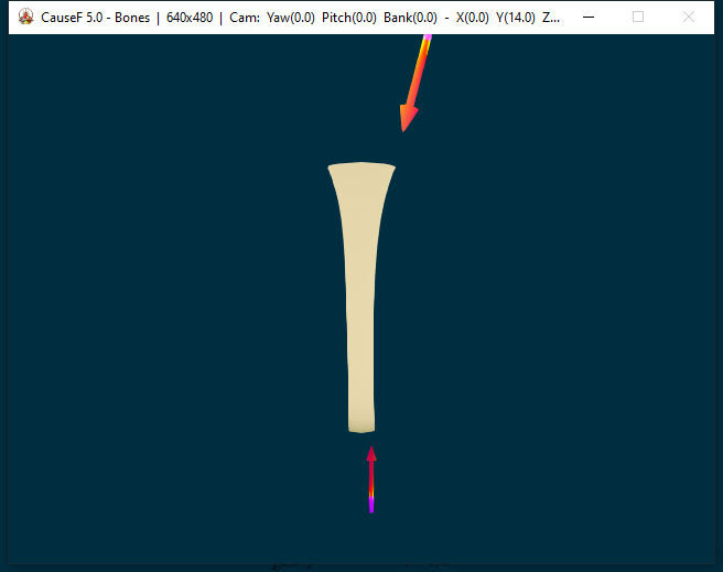
One or several activated force vectors have been defined in terms of their position, orientation and magnitude. The cylinder shape has been defined in terms of its radius (plus inner radius if a tube, but from now on simply referred to as 'radius'), and its height. The
cylinder's material has been defined by density, compressive strength, Young's modulus, shear modulus and yield strength.
Each force vector displays its projection towards the cylinder (like a ray), and its intersection with the cylinder surface, referred to as touch point. If there is no intersection, the touch point sphere is placed a distance away along the ray's direction, and the ray itself is not shown.
If vector effects are applied -
Phase 1:
The weight is calculated, where each height unit of the shape (eg, a height value of 20 in Bones properties translates to 200 units in the render section) is taken as a disc of height 1 x its area, then applying density.
Using compression strength, at each height layer from the top downwards the minimum radius required is ascertained in order to sustain the accumulated weight from above without causing compression. With the top radius kept as defined by the user, the subsequent radii could become smaller if still able to sustain the weight above, or they could become larger if the shape needs to be stronger at any layer (for rendering purposes the differences are smoothed out).
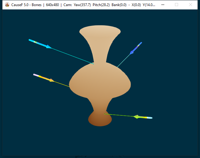
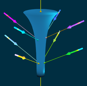 An example of vectors with their rays and intersection points on the surface of a modified cylinder (Phase 2).
Phase 2:
The intersections of the vectors' rays with the shape surface, ie, the touch points of all active force vectors, are calculated once again, this time based on the modified shape derived from the weight calculations. If there is no touch point, that vector is
discarded from now on.
If Weights only under Bones properties → Bones materials is ticked, the process ends there.
Phase 3:
The touch point parameters are stored.
Phase 4:
Each touch point is turned into a vector defined by its position, direction, magnitude.
Phase 5:
The touch point vectors have their components projected on to the x, y, z axis respectively and their values are stored.
Phase 6:
These components are combined with the rest of the Bones material properties to ascertain their impact on the cylinder, for each particular force vector.
Flexing is taken care of first, and the remaining impact value applied to the force vector's parameter set. The flex values are stored for later.
Phase 7:
Moving through the cylinder from top to bottom, the parameters obtained before are used to adjust the radius at each layer such that the impacts can be sustained at the radius' minimal size (in other words, so there is no impact).
If a force vector points upwards, its effects are calculated from its touch point towards the top, adjusting the radii along the way; then proceeding downwards again to readjust the radii in terms of the new weights.
Phase 8:
The flex values are averaged across the cylinder height for rendering later.
Phase 9:
The cylinder is rendered using the radii values along each height layer, and applying the flexure between its bottom and top according to the height layer's place within the height range.
Examples (A - modified attribute parameters based on Plastic, B - standard attributes for Sandstone, C - standard attributes for Bone, D - going for weird):
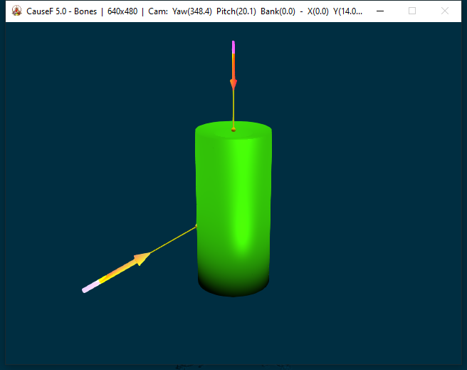
A. No effects applied. Two force vectors are active, defined by position, direction and magnitude. Their touch points indicate the intersection points with the cylinder. Here the cylinder is a tube, starting with the Bones materials Plastic presets
but then modified to: density 0.77 gm/cm3, compressive strength 706 MPa, Young's modulus 36.4 GPa, shear modulus 0.8 GPa, yield strength 434.9 MPa.
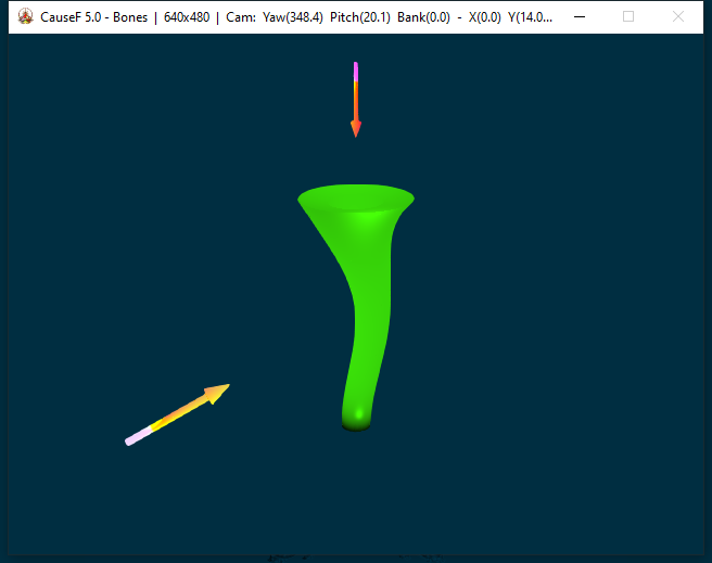
A. Vector effects applied. Vector yellow projects its force from the left and upwards, causing pressure from its touch point upwards but causing less pressure downwards. It also pushed the shape to the right causing a certain amount of flexure. Vector red
pushes from the top downwards. That pressure also causes a certain amount of flex, adding to vector yellow's impact. Since the initial radius (outer and inner) was relatively large, the diameter of the cylinder
decreases because all the loads can be sustained. The extent of flex seen derives from the given yield strength, that is the amount the shape can accommodate and still revert to its original form. The radii along the cylinder's height are sufficient to
support the combination of flexure and loads.
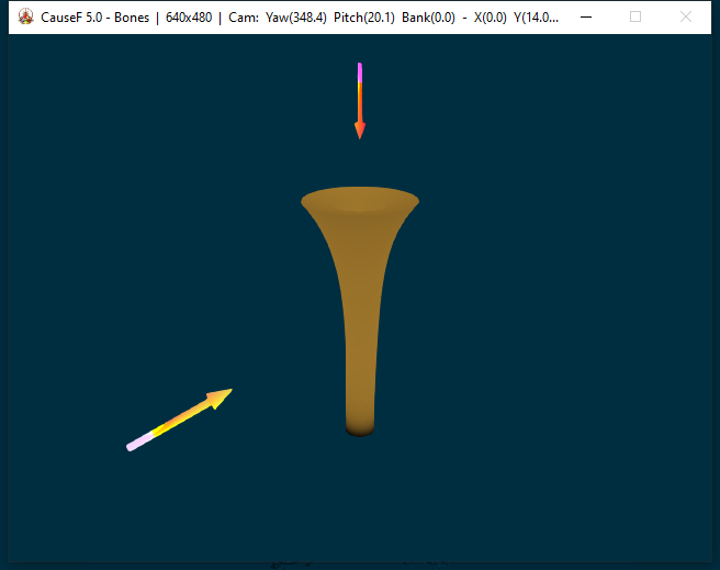
B. Compare with the same vector effects applied, now using Sandstone presets: density 2.6 gm/cm3, compressive strength 120 MPa, Young's modulus 38.0 GPa, shear modulus 0.4 GPa, yield strength 20.0 MPa. The material is also capable of supporting
the loads with smaller radii than initially given, but the density is the overriding factor and there is only a slight flex to the right.
C. A typical arrangement using the Bone presets (general values, not all bones are the same): density 1.1 gm/cm3, compressive strength 100 MPa, Young's modulus 10.0 GPa, shear modulus 0.7 GPa, yield strength 80.0 MPa. Here the force vectors
could be the main loads acting on something like a thigh bone between the hip and knee joints: The weight of the body from above, the inherent weights from the top downwards, and a force from the bottom upwards representing the impact generated by, say, walking. The
result approximates an actual bone. Note: no allowances have been made for the joints themselves.
D. Definitely not a typical arrangement. An imaginary scenario with density 1.02 gm/cm3, compressive strength 294 MPa, Young's modulus 23.6 GPa, shear modulus 0.4 GPa, and yield strength 500.0 MPa. Suppose those four vectors act consistently on
something that evolves in response, with no body weight nor any ground effect to be taken care of (let's say in an aquatic environment) - this could well be the outcome. Note that despite the yield strength being at 500 and therefore making for a very forgiving
material, the flex is barely noticeable because the vectors more or less cancel each other out horizontally yet have a vertical impact.
![]() Key points
Key points
You can -
- make use of 10 force vectors to create an impact on a cylinder shape;
- activate any of the vectors selected;
- use four presets to start with vectors arranged in some manner;
- test all activated vectors in case they are too close to the shape;
- define the position, orientation and magnitude of a specific vector, or
- use a combination of active vectors to change their position, orientation, magnitude by a same value, or
- relative to the specific values of each vector;
- use one active vector as reference for position, direction and/or magnitude and snap any other vectors to those values;
- circle a single vector around the shape (keeping the same distance but changing the position);
- centre a single vector towards the shape (regardless of position, it will point to the vertical axis);
- use the undo and redo buttons to move between previously defined parameters, including their modes (such as Circle, Centre, etc);
- save and load data, reset the vectors to their default state;
- use hotkeys to interact with the graphics in the window (rotation, camera view, zoom, fly-by);
- set the parameters of the cylinder (solid, tube, radius outer and inner, height);
- view the shape as a wire mesh to see inside;
- further adjust the touch points along their x, y, z axes;
- define the material properties of the cylinder, or use the seven presets;
- use animation to watch the emergence of the vector effects from start to finish.
![]() Settings window
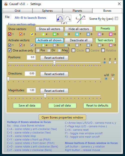
Settings window
Note: For the buttons etc to be enabled the Bones window has to be opened with Alt+B (the same applies to the Bones properties window).
Default settings are shown. Clock-wise from left to right, top to bottom:
(1) Undo/Redo buttons
Move backwards and forwards through the selections within this window. Includes the parameter values as well as the modes at the time (eg, vector selections, Pos, Dir, etc). The total number of configuration sets stored can be changed in Default
settings → Bones → Default limit for Undo/Redo entries.

(2) Scene fly-by (yaw)
Combined with the C+A and C+S hotkeys the scene rotates constantly, clockwise or anti-clockwise. All the other hotkeys are still useable, changing the camera view during the fly-by. See (20) Hotkeys - C+A and onwards.
(3) Force vectors setup - Show all vectors
All ten vectors are shown, either at their default position, orientation and magnitude, or whatever has been set by the user. They are visible, but not active.
(4) Force vectors setup - Hide all vectors
All vectors are invisible. Only visible vectors can be activated, and only activated vectors can be manipulated and take part in the effects calculations.
(5) Force vectors setup - Presets
Opens the Vector presets window (see below). Has four scenarios with all ten vectors pre-defined, any one of which can be deactivated and/or removed entirely later.
(6) Force vectors setup - Show vectors checkboxes
Show or hide a particular vector.
(7) Force vectors setup - Activate all shown
All visible vectors are activated, meaning they can be manipulated further and they participate in the effects calculations.
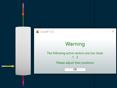 Warning message if vectors are too close to the cylinder (image at 70% of original size). In this case vectors 1 and 3 are too close. ((9) Force vectors setup - Test vectors)
(8) Force vectors setup - Deactivate all
All vectors are deactivated.
(9) Force vectors setup - Test vectors
Button acts as a toggle. Useful to check whether any vector is too close to the cylinder. Their distance has to have a minimal value for the effect calculations to work. Note that increasing the magnitude of a vector may bring its arrow point too close to
the cylinder's surface - it is the yellow highlight at the other end which identifies a vector's position, not its arrow. Although the vector's ray and touch point are not shown anyway in this case, their distance may not be readily identifiable if behind the cylinder.
(10) Force vectors setup - Activate vectors checkboxes
Activate or deactivate an individual vector. An active vector can be manipulated and it takes part in the effect calculations.
(11) Force vectors setup - One active only
If ticked, only one vector can be activated at a time, and therefore can be manipulated. If several vectors are shown, the rest are unaffected by the manipulations. The checkbox must be unchecked for combined operations (Pos, Dir, Mag, Circle,
Centre, Relative), see below.
(12) Force vectors setup - Pos
Has two uses:
(a) Snap vectors to position: For example, vector 2 has a certain position on the x, y and z axis and vectors 1 and 3 should be at the same position on either x, y or z. With One active only checkbox unticked and Pos ticked, and either the x, y or z (axis) radio button under Positions selected, tick the Activate vectors checkbox for vector 2 first and then the checkboxes for 1 and 3. In other words, the first selection becomes the reference for all the others.
(b) Move vectors together: First deselect One active only checkbox, tick the Pos checkbox, tick the Relative checkbox, select either the x, y, or z (axis) radio button. Then tick as many of the visible vectors as required to make them active. From now on the Positions slider will move all the active vectors relative to their own particular positions. If another radio button is selected, the vectors will have to be activated again.
(13) Force vectors setup - Dir
The same goes for defining the direction (that is, orientation) of active vectors. See under (12) Force vectors setup - Pos for the principle involved, except the Directions slider has to be used, and the u/d and l/r radio buttons
for up/down and left/right angles respectively.
(14) Force vectors setup - Mag
The same goes for defining the magnitude of active vectors. See under (12) Force vectors setup - Pos for the principle involved, except the Magnitudes slider has to be used.
(15) Force vectors setup - Circle
Tick this check box to move an active vector around the vertical (y) axis, maintaining its distance from the axis. Its direction will not change however. The movement starts from the vector's current position.
(16) Force vectors setup - Centre
Tick to change the direction of an active vector so it points to the vertical (y) axis. While ticked the vector can be moved along any of the axes and it will automatically point to the centre. Note that changing the direction will not untick this check
box, it has to be deselected and selected again for centering; however, applying a direction change once again, the vector will snap to the previous direction change.
(17) Force vectors setup - Relative
If ticked and (11) Force vectors setup - One active only unchecked, the positions, directions and/or magnitudes of active vectors can be changed relative to their current positions, etc. See (12) Force vectors setup - Pos and onwards.
(18) Force vectors setup - Positions
Move a vector along the x, y or z axis, depending on the x, y or z radio button selected on the right.
(19) Force vectors setup - Positions - Reset activated
All active vectors will be reset to their default positions.
(20) Force vectors setup - Positions - x, y, z radio buttons
Select the axis along which the vector should be moved.
(21) Force vectors setup - Directions
Change the direction in which a vector points, depending on the u/d or l/r radio button selected on the right.
(22) Force vectors setup - Directions - Reset activated
All active vectors will be reset to their default orientations.
(23) Force vectors setup - Directions - u/d, l/r radio buttons
Select the plane on which the vector should be rotated. u/d - up or down (pitch), l/r left or right (yaw).
(24) Force vectors setup - Magnitudes
Change the magnitude of an active vector.
(25) Force vectors setup - Magnitudes - Reset activated
Reset the magnitude of an active vector to its default value.
(26) Force vectors setup - Save all data
Saves all the vector definitions as well as all the cylinder and material attributes under Bones Properties → Bones dimensions and → Bones materials.
(27) Force vectors setup - Load all data
Loads the above data and applies them to the scene in the Bones window.
(28) Force vectors setup - Reset to defaults
All force vector definitions and all cylinder and material attributes are reset to their default state.
(29) Open Bones properties window
In the Bones properties window you can adjust the cylinder shape and the material attributes.
For the hotkeys to work, the Bones window has to have focus.
(30) Hotkeys - Esc
Any processes within the Bones window are stopped and the window is closed.
(31) Hotkeys - C+A
Makes the scene rotate anti-clockwise with the camera. When pressed the scene rotates, when released the rotation stops. Holding down the keys will gradually increase the speed. If (2) Scene fly-by (yaw) is ticked the rotation is continuous, it starts slowly and
becomes faster the longer the keys are pressed. Releasing the keys will keep the rotation going at that speed. Pressing C+S during rotation will first slow down the anti-clockwise rotation and eventually enter the clockwise rotation at ever increasing speed.
(32) Hotkeys - C+S
The same as above for a clockwise rotation.
(33) Hotkeys - C+X
With (2) Scene fly-by (yaw) unchecked resets the camera view to the original and/or previous value.
With (2) Scene fly-by (yaw) checked simply stops the fly-by. Rotation can be recommenced with C+A or C+S respectively.
With (2) Scene fly-by (yaw) unchecked again, from now on sets the camera view to the value at the last stop during fly-by. The camera can be reset to the default value with C+N.
(34) Hotkeys - C+Y
The scene rotates upwards (pitch).
(35) Hotkeys - C+U
The scene rotates downwards (pitch).
(36) Hotkeys - C+D
The scene rotates anti-clockwise (bank).
(37) Hotkeys - C+F
The scene rotates clockwise (bank).
(38) Hotkeys - C+Arrow keys L/R/U/D
The camera shifts to the left, to the right, up or down.
(39) Hotkeys - C+Page keys U/D
The camera shifts along the z axis, ie, zoom in or out.
(40) Hotkeys - C+N
The camera resets to the default view.
(41) Hotkeys - F1
Toggle. Maximum window on or off.
(42) Hotkeys - F3
Toggle. Wire mesh on or off. See also Bones properties → Bones dimensions → Reduce mesh to set the coarseness of the mesh.
![]() Bones window
Bones window
Default state is shown with three active force vectors and a generic cylinder shape.
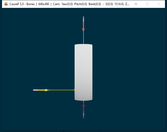
From the 800 x 600 window size upwards all the text in the title bar becomes visible:
From left to right:
- window size;
- Camera Yaw (around y axis);
- Camera Pitch (around x axis);
- Camera Bank (around z axis);
- Camera shifts along x, y, z axes;
- F3 wire mesh toggle on or off;
- FPS frames per second.
![]() Bones properties window
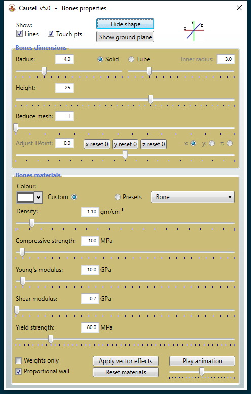
Bones properties window
Default settings are shown.
(1) Show - Lines
At first the lines (ie, rays) between the force vectors' arrow tips and their touch points are shown anyway, but when vector effects are applied they become invisible. Ticking that checkbox makes them visible again.
(2) Show - Touch pts
At first the touch points (ie, intersections) of the force vectors' rays are shown anyway, but when vector effects are applied they become invisible. Ticking that checkbox makes them visible again. Note however that the touch points are at the
position they were after the weight calculations per se have been applied before the smoothing process during rendering; they no longer coincide with the final modified surface since they have done their work.
(3) Hide shape
Toggle. Shows and/or hides the cylinder shape. Although the cylinder may not be visible, its configuration still exists and is involved in the various calculations.
(4) Show ground plane
Toggle. Shows and/or hides the ground plane. It is for visual reference only and does not participate in the calculations.
(5) Bones dimensions - Radius
Sets the radius for the cylinder. If the cylinder is a tube (ie, is hollow), it becomes the outer radius and is labelled as such. If (38) Bones dimensions - Tube has been selected, the radius must be larger than the inner radius.
(6) Bones dimensions - Solid
Renders the cylinder as a solid.
(7) Bones dimensions - Tube
Renders the cylinder as a - hollow - tube.
(8) Bones dimensions - Inner radius
Enabled if (38) Bones dimensions - Tube has been selected. Defines the inner radius for the cylinder. The inner radius must be smaller than the outer radius.
(9) Bones dimensions - Height
Sets the cylinder height. Note that a value of '25' here for example translates to '250' for the rendered cylinder; '25' matches the scale of the height coordinate for the force vectors (along the y axis) in the Settings window.
(10) Bones dimensions - Reduce mesh
Range is from 1 to 16. If at '1', every vertex point of the shape is part of the render process, if '2' every second vertex point is rendered, and so on. Note that the linkages between the vertices are not broken, any excluded vertices are merely stepped
over. It means that the resultant cylinder is no longer complete. If the hotkey F3 has been pressed, the wire mesh becomes thinner and what's inside may be more visible.
(11) Bones dimensions - Adjust TPoint
If vector effects are applied, the touch points can be further moved from their original x, y or z positions as a result of the erstwhile effects calculations. The effects are calculated once more. Which position is adjusted depends on the x, y or z radio
buttons to the right.
(12) Bones dimensions - x reset 0, y reset 0, z reset 0
Any adjustment along either the x, y or z axis is removed.
(13) Bones dimensions - x, y, z radio buttons
Select adjustment along the x, y or z axis respectively. See (11) Bones dimensions - Adjust TPoint.
(14) Bones materials - Colour
Selects the cylinder's colour if (15) Bones materials - Custom is selected. If (16) Bones materials - Presets has been selected, the colours are predefined.
(15) Bones materials - Custom
No materials presets are used.
(16) Bones materials - Presets
The definitions below (density, compressive strength, Young's modulus, shear modulus, yield strength) are preset according to the selection in the dropdown box, including the colour. Presets are available for seven general types: bone, concrete,
glass, plastic, sandstone, softwood, steel. All the definitions (excluding the colour) can be modified further. Note that the preset values are more or less averages for the broadly defined material properties.
The following definitions of material attributes are based on the sources listed under Copyright and credits, references, history.
(17) Bones materials - Density
The mass of a unit volume of a material substance. In other words, the measurement of how tightly a material is packed together.
Range: 0.4 - 10.0.
(18) Bones materials - Compressive strength
Compressive strength is the maximum compressive stress that, under a gradually applied load, a given solid material can sustain without fracture.
Range: 10 - 3000.
(19) Bones materials - Young's modulus
Young's modulus is a measure of the ability of a material to withstand changes in length when under lengthwise tension or compression. Sometimes referred to as the modulus of elasticity.
Range: 0.1 - 300.0.
(20) Bones materials - Shear modulus
Shear modulus, or modulus of rigidity, is defined as the ratio of shear stress to the shear strain.
Range: 0.1 - 150.0.
(21) Bones materials - Yield strength
Yield strength represents the stress at which a material begins to exhibit plastic deformation. At that point it undergoes permanent or irreversible changes in shape when subjected to an applied load.
Range: 0.1 - 500.0.
(22) Bones materials - Weights only
As mentioned under Process → Phase 1, at first the weights of the height layers are used to modify the cylinder shape. If ticked, the modification process ends there. Useful to ascertain if all the force vectors still lead to intersections
with the cylinder surface before continuing with the rest of modifications.
(23) Bones materials - Apply vector effects - Remove vector effects
Toggle. The effects of the active vectors as defined in the Settings and Bones properties windows are calculated to modify the cylinder accordingly. While vectors, cylinder properties, etc can be
redefined with the vector effects being applied, sometimes a particular redefinition interacts within a different phase of the calculations and so may not affect the result comprehensively. Therefore it is best to remove and then apply the effects again.
(24) Bones materials - Play animation
The changes in the cylinder surface are rendered step by step. Because the underlying parameter values are in sync with the calculation phases, the animation is in line with the phases. Note that this kind of animation is not based on frame rates (such as
in cartoons for example). The extent of the steps can be changed via the slider underneath - smaller steps to the left (slower animation), larger steps to the right (faster animation).
Range: -1.0 to +1.0.
(25) Bones materials - Proportional wall
Enabled if (7) Bones dimensions - Tube is selected. If ticked and vector effects have been applied, the inner radius from the top downwards (including the cylinder's bottom cap) is defined in terms of the initial ratio between outer and inner
radius. If unticked, the initial value of the inner radius is used in the effects calculations. As a result this usually means a relatively larger inner radius when ticked - a more 'natural' configuration.
(26) Bones materials - Reset materials
Resets all the material attributes to the default values, for Custom and Presets.
![]() Vector presets window
Vector presets window
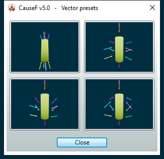
Select any of the four vector configurations, they use all ten vectors. Modify from then on as required. To bring back the original positions, directions etc, apply (7) Force vectors setup - Activate all shown in the Settings window with (11) Force vectors setup - One active only unchecked, then apply (19) Force vectors setup - Positions - Reset activated, (22) Force vectors setup - Directions - Reset activated, and (25) Force vectors setup - Magnitudes - Reset activated.
If only some of the vectors should be reset, activate those vectors using the (10) Force vectors setup - Activate vectors checkboxes, then apply any of the Reset activated buttons.
![]() Tips and hints
Tips and hints
As the Bones module features many automated processes behind the scenes, given the nonlinear nature of the program there are occasions when a result doesn't appear as expected because the processes did not interact the way they could have.
No damage has been done and the solution is simple. Following is a list of common occurrences.
Vector direction
When repositioning a vector such that it moves from the negative to the positive x or z axis (or vice versa), the direction angle may not be in line with the coordinate system of all the other vectors in that other half.
Solution: before starting the reposition, tick (16) Force vectors setup - Centre first, then move the vector. It will now point to the centre within the appropriate coordinates. Then change its direction if required.
No apparent vector effects (1)
If a vector does not seem to result in an effect when vector effects are applied ((23) Bones materials - Apply vector effects - Remove vector effects), this is because after the weight calculations with the cylinder shape now modified, the
vector's ray no longer intersects with the cylinder, or it is now too close to the cylinder.
Ticking (22) Bones materials - Weights only and applying the vector effects once more will make that obvious - the relevant vector will no longer show its ray and the touch point is some distance away (zoom out or rotate the scene if necessary). Tick (1) Show - Lines and (2) Show - Touch pts at the top of the Bones properties window.
Solution: reposition the relevant vector and/or change its direction until there is an intersection point. Ticking (22) Bones materials - Weights only makes that easier.
No apparent vector effects (2)
While vector effects are being applied and the vectors and/or the cylinder or material properties are being modified, the overall effect may not have taken any of those redefinitions into account because the effects are applied interdependently (a side effect
of nonlinearity). Can also happen when changing from a solid cylinder to the tube version. The same applies during animation.
Solution: remove and apply the vector effects again.
The combined vectors functions don't work
When using any of the (12) Force vectors setup - Pos → (b) and onwards, the vectors don't snap to the reference vector, or they don't move relatively to their current position, direction, etc.
Solution: please ensure the steps as outlined under (12) Force vectors setup - Pos → (b) ... are followed exactly since the sequence is important. You can also use the (1) Undo/Redo buttons to step back.
© Martin Wurzinger - see Terms of Use